Climate Cube
A small room on the first floor is where I spend my free time tinkering with design, code and electronics. Although the space is great, it is hard to get the climate right. This sparked the idea to measure the climate conditions in my study room to get some actual data to compare with my feeling of dissatisfaction about the temperature.
In my search for a solution I came across a nice Instructable for an IoT Weather Station. It shows a compact setup with breakouts that come with ready made software libraries. Perfect to quickly get started.
Components
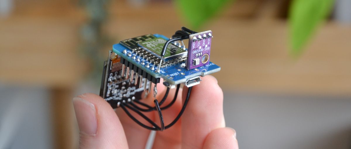
I have used the same electronic components as mentioned in the Instructable and added a Li-Po battery and charging module to make it portable. At first I wanted to use an Adruino Nano for the microprocessor, but the WiFi capabilities of the ESP8266 better suited my need for a stand-alone (untethered) solution.
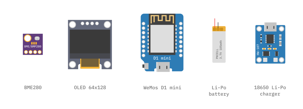
| Bosch BME280 Temprature, Humidity, Pressure sensor |
| OLED Display Module SSD1306 128x64 |
| WeMos D1 Mini v2.0 ESP8266 |
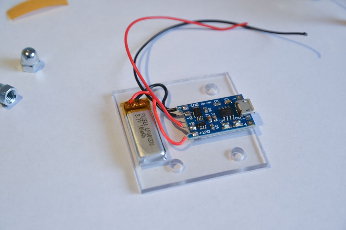
| Li-Po battery 105 mAh |
| Micro-USB Li battery charger 5V, 1A. 18650 |
Testing the circuit
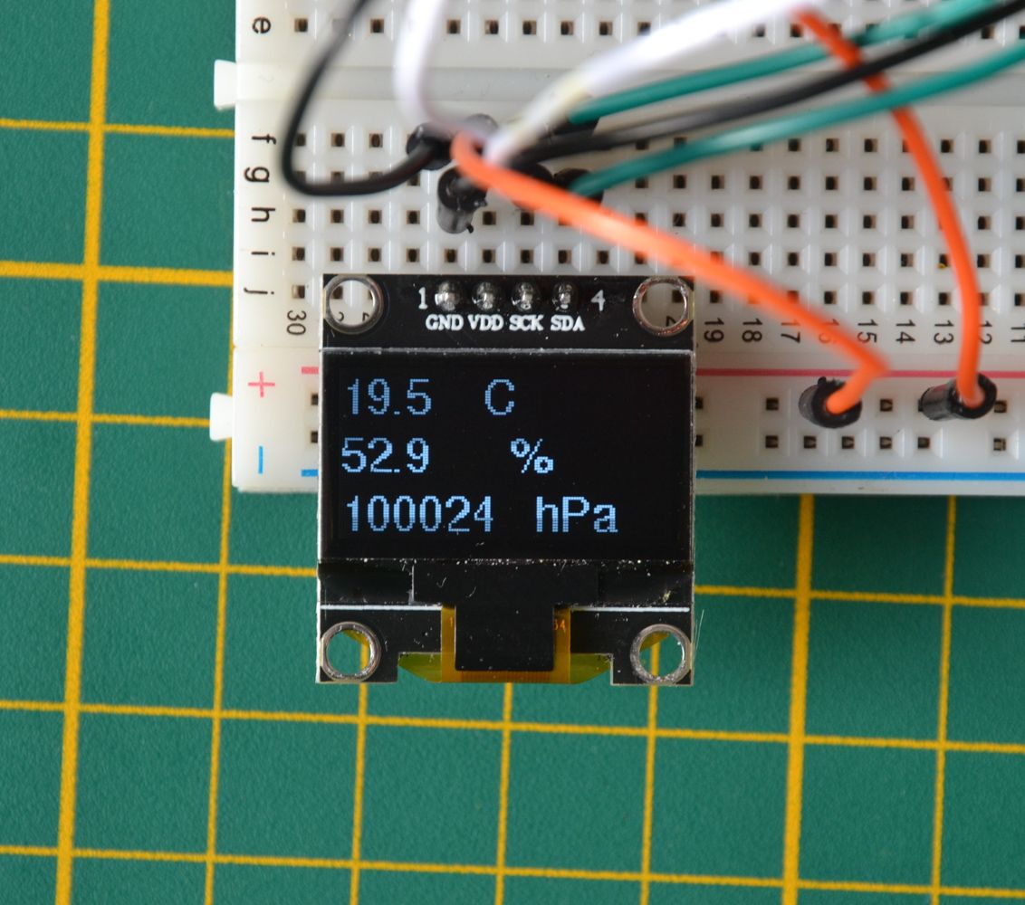
Both the BME280 and the OLED display breakout communicate with the WeMos D1 mini over I2C. The BME280 worked at first try with the example Arduino sketch and I was impressed by the sensitivity of the altitude measurement that detects differences sometimes smaller than 1 meter.
To get the display working I had to change the I2C address to 0x3C instead of the default 0x3D. It took some time to troubleshoot why the display was not working, but the addressing problem itself was quickly solved with an I2C scanner.
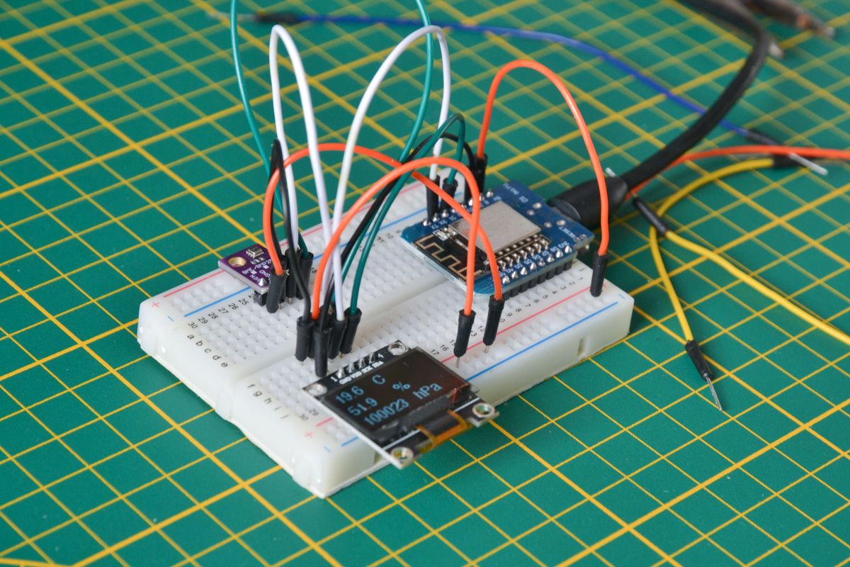
Connecting two breakouts on on the SCL and SDA pins worked perfectly. Before using the OLED display, I tried a larger TFT color display via SPI, but could not get it working. A stange behaviour of the Wemos D1 I then discovered was that connecting the CS (Chip Select) pin sets it in firmware flashing mode which breaks the serial connection. You can solve this by using another pin, but eventually the OLED display over I2C seemed the best solution.
Connecting the pieces
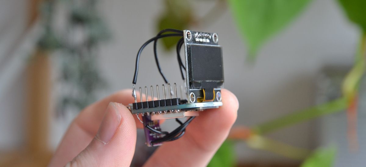
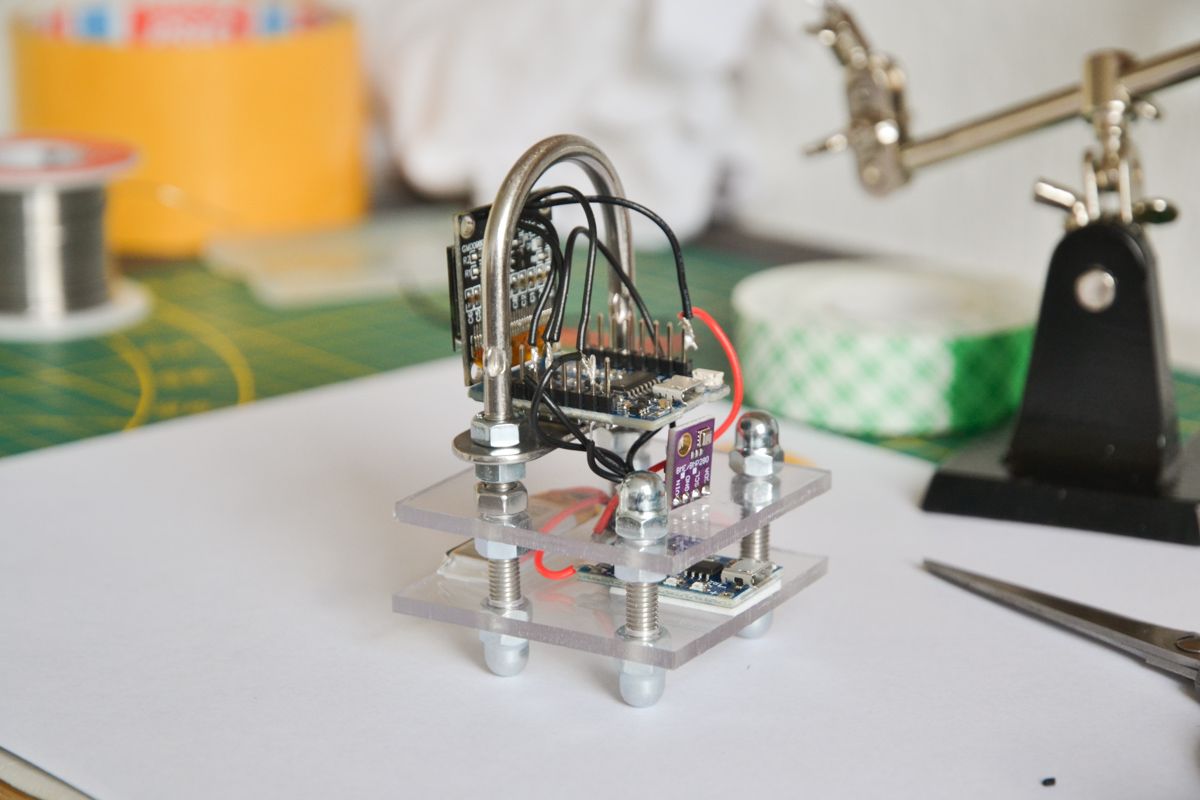
Now the components are working as together as they should, it was time to solder them together in a nice little package. I connected the display and the sensor at two different sides of the Wemos D1 mini to make it easier to solder two wires on the same PTH pin. Although later it would seem that this makes it a tiny bit harder to mount it firmly in a supporting frame.
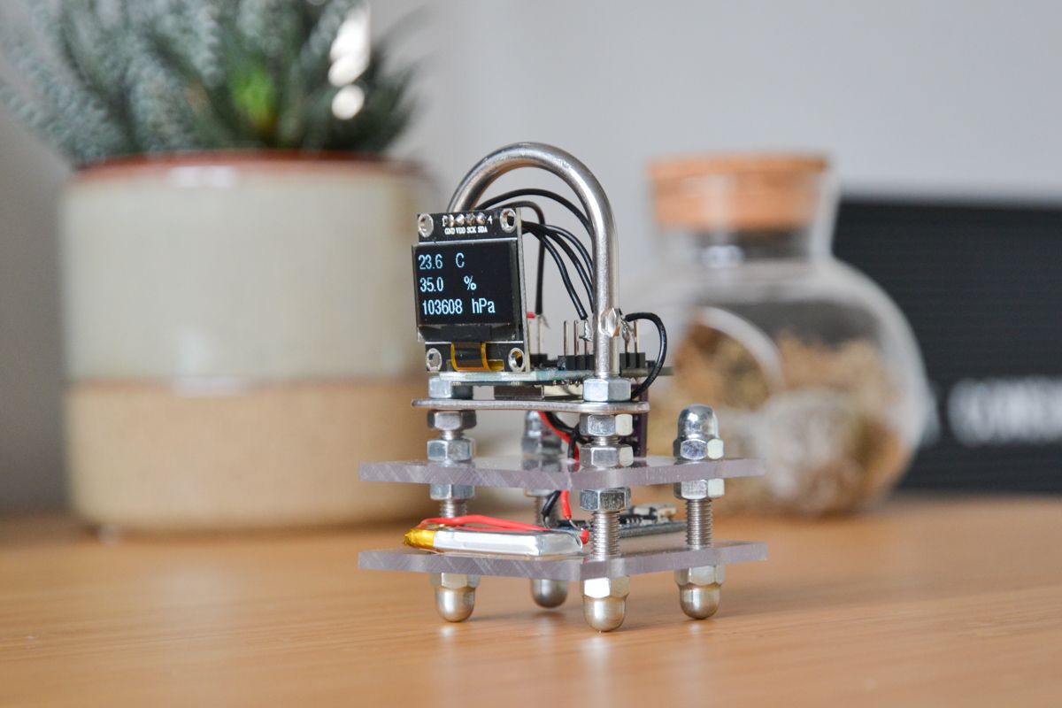
Frame the solution
The instructable uses an unconventional frame made of brass plated iron rods that are soldered together in a cube. The rods also function as current conductors to enable the circuitry. I decided to go for a slightly more stable and robust frame by making it from perspex plates and M5 threaded studs. The battery and charging module are mounted together on the bottom plate, while the Wemos sits on the plate above.
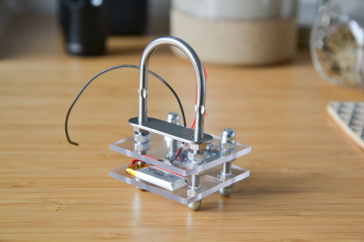
A nice happy accident was that I found a bracket with threaded ends that precisely fit this idea. The plate that came with the bracket was the perfect surface to mount the board on and the arc protects the fragile orthogonal connection between the display and the Wemos D1 mini.
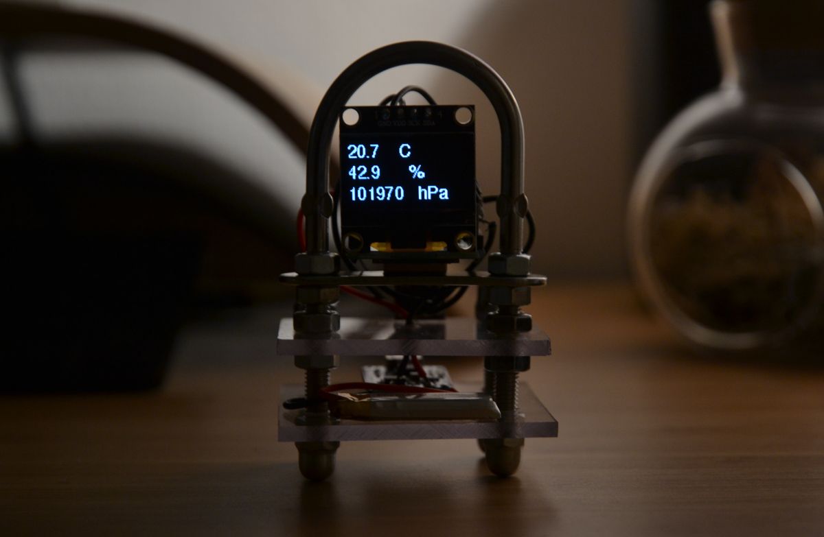
Result
I am quite happy with the result and the aesthetics of it. In the first few days of using it I already came across some improvement points:
- The battery's capacity of 105mAh makes it lasts only 30 minutes because the display draws considerable current. Improving the battery capacity or implementing a sleep mode would help to keep it portable for longer.
- Data can now only be gathered over serial communication. An improvement would be to have continuous data collection over WiFi, but in combination with the display it will be a challenge to keep it stand-alone.
Let's see in the coming days whether the climate is indeed as moody as my mind thinks it is.